,

Mugshot
Click for home

Peter C Grossi
The Workshop


Contents

Hardware Design
Software Development
Microcode Development
Production
Test Equipment
Calculations
Laboratory Equipment


Hardware Design


FreeCAD

FreeCAD

FreeCAD 3-D design
This is the principal tool I use to design plastic printed components. It is free software, running under Fedora linux. But it is very versatile with all sorts of plug-ins for screw threads, gears and many other things.
Being fully WYSIWYG it is easy to rotate and expand the view to check everything as you go along.
It can be used in a number of ways:
* I use it mainly to build designs from "primitives" such as boxes, spheres, cones etc., which I add and subtract to produce the required shapes and voids.
* For complex shapes I "draw" them in 2-D and extrude them orthogonally or along a curved line.
* Components can be parameterised, so that if the dimensions or position of one element is changed then everything that has to fit with it automatically changes. For one particular project which involved concentric components this saved a lot of time and prevented errors.
FreeCAD produces stereo lithography (STL) files, as well as other export formats for compatibility. The STL files can be downloaded or published for others to print their own components.They are not easily edited but they are independent of the printing machine used and are therefore a widely used means of publishing 3D designs for printing.
Where they are of interest such designs for my own projects will be published on this website for downloading.

KiCAD

Project control

KiCAD project screen

Schematic editor

KiCAD schematic design

PCB editor

KiCAD PCB tracking design
This is free software running under Linux, and provides a comprehensive set of tools for electronic design,PCB layout and files for PCB production.

The Opening Menu accesses a number of tools for the following:
* Preparing schematics from standard components (of which there is a massive library)
* Creating or adapting custom variations from the symbol libraries provided
* Laying-out PCBs with extensive facilities for specifying track dimensions, through holes etc.
* A footprint editor to create or modify custom component dimensions and lead arrangements
* A viewer for standard Gerber files, which are prepared from the PCB editor and used in the production of PCBs.
* Other housekeeping functions

The Schematic Editor uses drag-and-drop from drop-down menus of standard components. Being WYSIWYG it is easy to see how the connections are built up. Tracks can be labelled for clarity (and for identification on the PCB editor), so that confusing tangles on the schematic can be avoided by asigning the same label text to tracks that do not have to be shown as connected.
Component footprints can be assigned and bills of materials prepared in a variety of formats.
The BoM communicates directly with the PCB editor to ensure all components are correctly shown for placement.

The PCB Editor picks up the components automatically from the schematic editor. There may be tools for automatic layout and tracking but I don't use them.
The component symbols can be dragged into position using either metric or imperial snapping, and tracking "dropped" from the side menu to connect as required. Errors are avoided by ensuring that tracks can only be connected according to the schematic, and the pads are highlighted for clarity.
The track and hole dimensions are specified in a setup page, and signals (tracks named in the schematic) can be assigned to any of number of user-defined variations. Individual sections of track can be separately assigned different dimensions, such as may be required to squeeze between 0.1" component pads.
There are a large number of layers available, including copper, solder masking, ink printing, edge-cutting and user comments, any of which can be printed in standard (e.g. Gerber) format for automated production.
For my own construction I use one copper layer, a drill file and an edge-cut file, which I convert into gcode for the engraver.


Software Development


Eclipse

Eclipse IDE

MPLAB-X Development Environment
This is a development environment for large applications, and is entirely free. It can be used to build a variety of different languages but I use it on the Linux system to develop commercial applications with Java.

Java Language

Java

Java logo
This is a very powerful and widely supported object-oriented programming language. It is not a language for inexperienced programmers but it's structured and disciplined data and process design, properly used, ensures robust and maintainable software. It is my weapon of choice for commercial applications.

It is not fully compiled, which means that the issued applications can run under different operating systems without modification. This gives it a big advantage over many programs that are restricted to Windows, Linux or Apple Mac, or which have to be separately developed and end up at different development (functional) levels for different oparating system users.
In order to run a Java application the user's machine needs to have a Java Virtual Machine (JVM) installed. This is provided free by Sun Microsystems for all platforms free of charge, and is issued with the Java software for a very straightforward installation.
Java is supported by a great many independently developed special libraries for communications, graphics, maths etc. but for me the most important are the libraries providing Structured Query Language (SQL) and database management, both of which provide a core of extremely reliable data management for commercial use.

Python Language

Python

MPLAB-X Development Environment
This is a widely used object-oriented programming language. Similar in some ways to Java but much simpler.

It has a confusingly similar syntax to Java but, while easier to use for less experienced programmers, can cause problems when switching back and forth. I adopted this language when developing applications to run on a Raspberry Pi, for which this is the preferred application language.

For comparatively simple applications this is a good and well documented language and is well supported by independent developers of useful function libraries. Poperly used, it can provide a base for some very useful applications. I would continue to use this for applications to run on a Rasperry Pi, but probably not for anything else.


Microcode Development


MPLAB-X


IDE

MPLAB-X Development Environment

IPE

MPLAB-X Programming Environment
This software is provided free by Microchip to support the use of their PIC range of programmable chips for embedding in devices.
Their range of chips is continually extending, but I use the cheap and simple 8-bit RISC (Reduced Instruction Set Computing) devices as they provide a very good alternative to otherwise complex and bulky combinational logic.

The software comes in two separate parts. One is ued to prepare the source code, check it and assemble it into Hex code, as required to transfer into the programmable components. The other part does the job of transferring the Hex code and checking that it arrives as it should.

The IDE (Integrated Development Environment) is used to prepare and assemble the source code.
It can be programmed in C, MASM or MPASM but for my purposes C does not give the required clock-level control for the signal timing required for my designs, but MASM (Microsoft Assembler) is simple, traditional and widely known to device programmers.
Unfortunately Microchip has superceded it in the recent issues of the IDE in favour of MPASM. This has an extended instruction set with improved directives but is incompatible with the large archive of programs that I continue to support.
Therefore I use a version of the program that is now several years old, and which is provided with the MASM-compatible assembler I need.
I have been using an early version of this application under Windows7 for many years but have now tranferred it to my Fedora linux computer.

The IPE (Integrated Programming Environment) is required to transfer the Hex code into the device.
It uses a USB dongle (which unfortunately has to be paid for, but it is not expensive) to hold and connect the device. There are versions of this, but for many years I have used PiCKit-3 which still does the job perfectly well.
With a suitable connector the devices can be programmed on board their PCB but I don't use that. The PiCKit can be configured to provide power to the device for programming, which makes it convenient to use.

Both these applications also work from my Fedora linux computer, so I have recently been happily able to migrate all of this from Windows onto a much more reliable platform.


Production


3-D Printing

Anycubic

MPLAB-X Development Environment
It must be said that 3-D printing is hardly a low-cost production environment, but in recent years companies have set up production units with multiple printers to produce small-ish quantities with very much lower setup costs than the more established injection moulding method. 3-D printing is also more suitable for designs with complex voids, which would otherwise have to be assembled from several parts.The range of materials available for 3-D printing is surprising, and even some suspension and engine parts are made of titanium for formula 1 cars.

Some years ago I started with a very basic build-it-yourself machine made of perspex and MDF. It was surprisingly robust for it's simplicity, and the machines that work straight from the box were rare - the Reprap community were the developers and required support. I tried it out of curiosity, and had to download the Arduino software (and the software loader) from the Reprap community.
But it was too much of a fiddle for regular use so it had to be replaced.

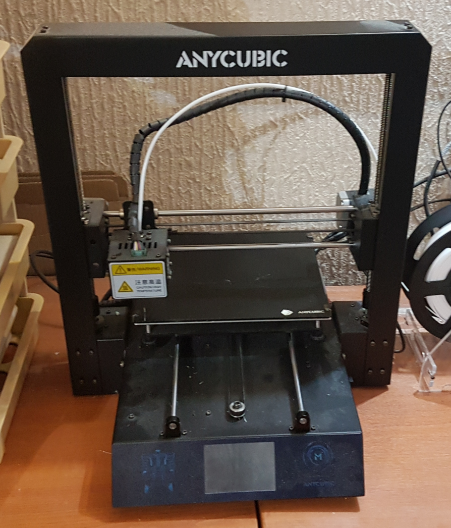
The supply picture changed dramatically over a few years, with several companies marketing cheap and easy-to-use machines. So in 2019 I decided not to build a better one for myself, and got the Anycubic. This worked straight from the box like all the standard printers available now, and it gives very reliable service over a build plate about 200mm square.
It doesn't have fancy things like automatic bed levelling, but I find I can get on perfectly well without it. It also runs stand-alone from memory cards loaded with GCode files.

Ultimaker Cura

File Conversion
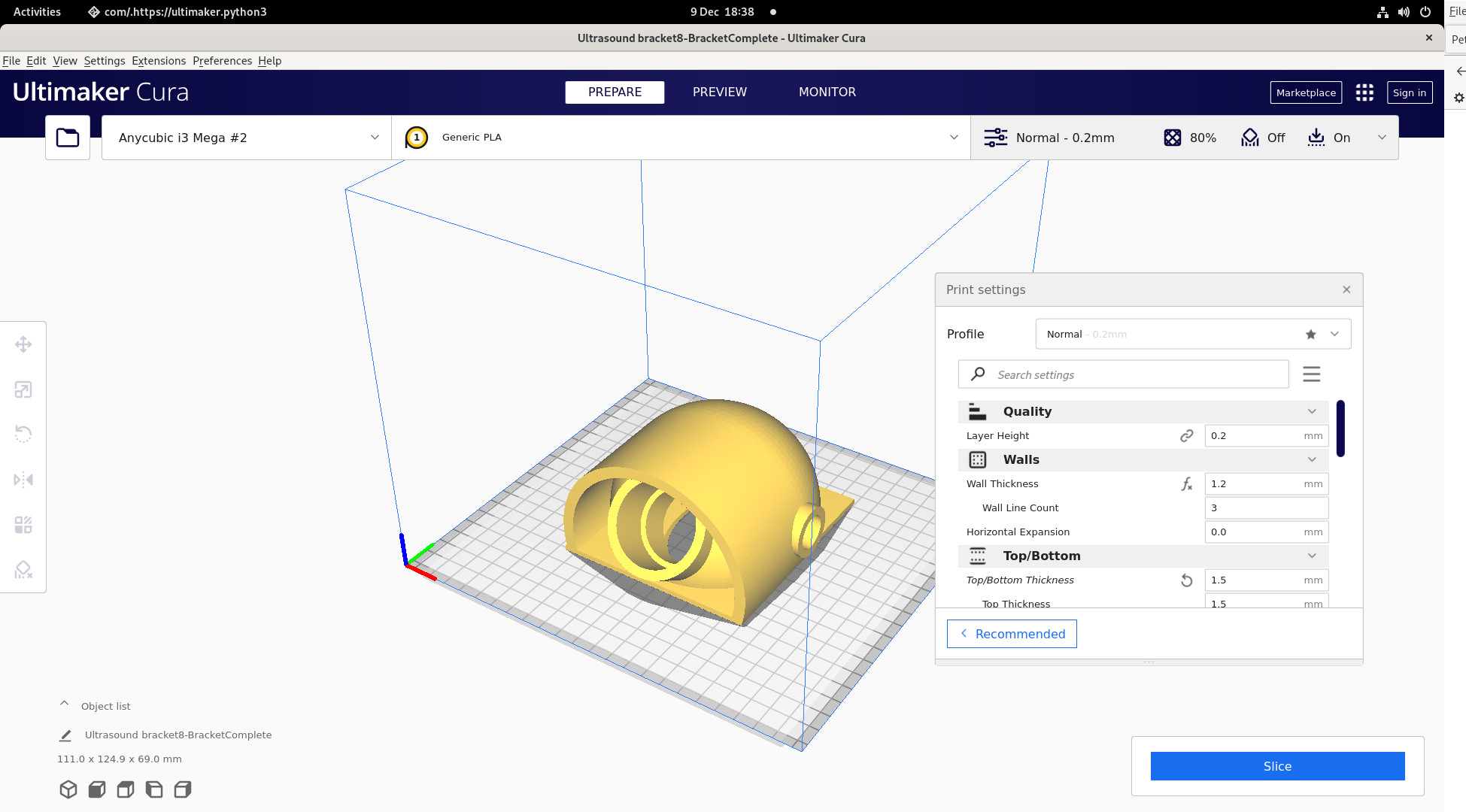
This application software has been developed by a company that designs and markets 3-D printers, but it publishes the application free. It can be set up to work with with many brands of 3-D printers, and I run it on my Fedora linux computer.

There are alternative programs (such as slic3r) but this is very popular and seems to work very well for the sort of things I do.
It takes in a STL file (such as prepared with FreeCAD, or downloaded from a developer) and converts it into a GCode file that can be used by 3-D printers and other production equipment. When using Cura the characteristics of the intended printer, and the type of material being printed (e.g. PLA, ABS, nylon, even chocolate) must be specified, and a suitable file is prepared for the printer to use.
This process only needs to be done once to print many identical copies, but needs to be repeated with different settings for different printers.
The component being printed can be rotated, scaled or duplicated as required from the original STL file.

PCB Prototyping

PCB Engraver

PCB Engraver

Sample PCB

Sample PCB
For many years I was obliged to build my circuit boards from padboard, and hand-stitch all the wiring.
While I learned to make a neat and robust job I found it time consuming and generally tiresome, so I decided to make proper PCBs. But I had problems with the conventional photo-chemical processes, notably that I couldn't prepare a dense enough photographic transparency to give reliable exposure. It also left me with the problem of drilling many holes with sufficient accuracy, which also promised to be tiresome and slow with my drill-press mounted Dremel and mini-workbench.

So I decided to use an engraver that could be controlled with GCode files in the same way as a 3-D printer. Software is available to convert the Gerber format files produced by the PCB editor (see above) for the tracking and the drilling. But when I did some mesurements and calculations it promised to be prohibitively expensive - at least 4 figures Sterling for a commercial unit.

The requirement is very different from a 3-D printer, which are inexpensive and may look similar in structure:
* When printing, there is no lateral force on the print head as it is only laying down a string of melted plastic. An engraver has substantial lateral forces.
* It needs to be much more accurate. I set a tolerance limit of 5 microns (compare with 50-100 microns for 3-D printing).
* It needs a strong motor to ensure consistent engraving, which is much heavier than a print head.
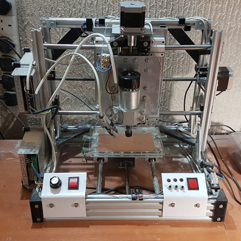
Taking these things and others into account it became clear that I couldn't buy an engraver or adapt a printer, and had to design and build my own, as pictured.
The overall cost was about £300, and I avoided the high cost of Acme screw units with 8mm threaded rods. But these did not come with standard anti-backlash followers, so I had to design those to suit the loads expected.

As can be seen in the picture, the construction is from simple 5mm aluminium plate and extrusions using captive nuts. The stepper motors are rather larger than usually found in printers, and the guide rods are much stronger (12mm stainless, compared with 8mm).
Having limited workshop facilities I made some critical components with the old 3-D printer, as seen in black, these include corner braces, guide rod support blocks, power unit clamps and cable clips.

The only serious problem was overcoming the natural curvature of the PCB blanks. When engraving with a cone-shaped cutter the slightest variation in depth (Z axis) results in substantial variation in cut width. A Z-axis consistency of better than 0.05mm is essential, but even with various clamps this could not be achieved.
I used a standard CNC card to control the machine, but it did not have bed-levelling capability. Eventually I overcame this problem by preparing a bed-levelling routine which applies geometric corrections to the source files.

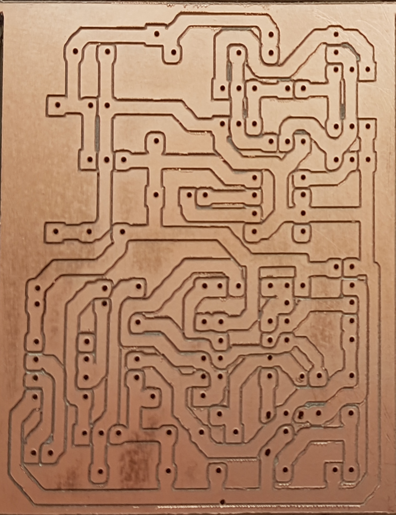
The results are now very good. From the files prepared by the PCB editor the machine engraves, drills and cuts out from the blank, all precisely registered, when fitted with the appropriate tools.


Test Equipment


Signal Analysis

Pico Oscilloscope

Pico
When I first got back into electronic design I bought a secondhand oscilloscope with dual trace and twin timebases. A Philips device, it was not unlike the Tektronix equipment I used during the 1980s in Ferranti. Limited to 50MHz bandwidth it matched the logic components (e.g. TTL and CMOS) that I used, and the twin timebase allowed expanded views of data packets. It did a number of years of very good service but it was inconveniently bulky and very much out of date. So as I got more heavily involved in digital and analog design I needed something more versatile.

The Pico range of digital 'scopes offered many attractive options. They are not cheap but they do their job. I went for a twin analog version with 16-bit digital channels and 200MHz bandwidth. I have used it for several years with a Windows 7 laptop, and now use it with my Windows 10 laptop.
The facilities offered by digital 'scopes is transformational. Quite apart from using a much larger screen (from which snapshots can be captured for documentation) it provides the usual expanded traces, pre-triggering, trace storage, on-screen measurement of time and voltage, frequency measurement (and variation), arithmetic analysis, and many other things. It even has a versatile test signal generator.

Signal Generator

FeelElec FY6900

Pico
Another thing I needed for my design work was a signal generator. I started with an old 50MHz square-wave generator with dual timebases so I could generate simple data packets but this wasn't reliable so it eventually had to be replaced.

This instrument, made by a company in China that has more or less cornered the market for inexpensive but versatile instruments, provides a range of analog waveforms as well as digital. It was very well reviewed on line by people who seemed to know what they were doing.

With dual timebases, external triggering and synch signal it does everything the old one did, and a lot more.

It is rated up to 100MHz and while It doesn't produce very square logical outputs above about 60MHz, and the signal amplitude is below TTL specification at higher speeds, that's fast enough for what I need.

Logic Testing

Logic Probe

Old probe New probe
While I was at Ferranti, one of the most useful hand-held devices was a logic probe. These were like pens in the hand and flashed a light when they saw a pulse in a digital circuit.

Their operation is a lot more complicated than at first it seems. They not only indicate whether a logic signal is a "strong" high or low (or neither), but if they see a single, very narrow pulse they flash a light long enough for you to see it.

My own research finds that, to see a LED flash in a normally-lit office requires a duration of at least 25ms. To see a LED blink off requires a longer time of at least 30ms. It is often the case that one needs to see a single pulse (high or low) in response to something, and this can be difficult to capture reliably by other means, particularly when you are away from the lab bench.

Where there is a continuous stream of pulses the light needs to blink at a rate that can be clearly seen, rather than show a continuous dim light. So the device makes no attempt to indicate the frequency or density of rapid continuous signals.

Although logic probes are cheap and easily available now, they used to be more expensive so I made it an early challenge to design and build my own, inside a length of 20mm plastic tube, and it has been very useful.

Now that I have the means to produce plastic containers to my own design, and can produce a proper PCB to build it on, I have designed and built another one, that doesn't look like a piece of bathroom plumbing.

The new one uses a programmable IC to replace the combinational logic, which makes the whole thing much more compact. The trick was to use a processor with an instruction rate of only 5MHz to process signals of 50MHz or greater. In view of the commercial availability of cheap Chinese units it might seem unnecessary, but it was an interesting and successful challenge.


Calculations


Slide Rule

My Ancient Thornton

Thornton
This dates back to the mid 1960s when it was the current technology for calculations that didn't need the precision of 7-figure "log" tables and it served me well as a student.

It's not the most expensive model, but it has all the usual things for multiplication, division, squares and cubes, trigonometry, exponentials and logarithms. There are also some tricky little scales that give extra precision for trigonometry.

The reverse has a Pi offset for quick circular calculations, and metric and imperial measuring scales.

I dragged it out of retirement recently just to play with, and discovered that for nearly all purposes it gives an adequate precision (3 sometimes 4 digits), and usually a lot quicker to use than a scientific calculator on screen or mobile phone.

It is now in fairly constant use.

I also have a cheaper USA-made Pickell, but it is not as easy to read or as versatile.

Flight Computer

ARC1 Flight Computer

Flight Computer
Flight Computer
I don't often leave the ground these days, except to change the occasional light bulb, but when I was learning to fly, this little beast helped me with all the necessary calculations for flight planning.

The core function of this specialised slide rule combines rotational and sliding motions to perform vector algebra. It calculates the variation from the direction the aircraft is pointing to the actual ground speed and direction, given a known cross-wind and aircraft air speed. Or it calculates the required heading given the required direction and the known wind.

The slider can be flipped according to whether the aircraft is going at low or high speed. In a single-propeller 2-seater I was emphatically in the low speed (below 150 knots) bracket.

The reverse side performs several different jobs.

  • The main outer scales are the same as a circular slide rule, for performing simple multiplication and division. The scales are also marked in minutes and hours to calculate flying time from speed and distance. And fuel requirement from known rate of consumption and flying time.
  • Another scale converts fuel volumes.
  • Outer scales provide fuel quantity calculations from specific gravities for volumes in UK gallons or US gallons and weights in pounds or kilos,
  • Other markings allow easy conversions between units of distance (feet, yards, miles, nautical miles and kilometers). In flight, distances over the ground are specified in kilometers, distances in the air in nautical miles, and heights in feet!!!
  • Calculating glide path or climb gradient can be a nightmare with these disparate units, so the scales can be used for this as well.
  • The Altitude windows calculate height corrections from the instrument reading to the actual height. This takes into account variations in local barometric pressure, the pressure altitude (the height at which the barometric pressure is 1013 millibars) and air temperature. All of these can change during a flight, although I was never in the air long enough, high enough or far enough for it be be significant.
  • The indicated airspeed can be in error when the atmospheric pressure changes, which depends on the height and air temperature. So there is a window for that as well.

Laboratory Equipment


Bench Drill

Dremel

Dremel
The Dremel is far more than a simple electric drill, having tools for polishing, grinding and cutting among others

But the Dremel bench press did not get good reviews so I use a Proxxon branded item, together with a precision cross slide. The press is great just to hold the drill steady for hand-held work as well as getting holes drilled exactly where I want them. The cross-slide makes sure holes line up properly, or pieces get cut in a straight line.

Unfortunately the Proxxon stand didn't fit the Dremel drill, so it needed a bit of hidden surgery.

Precision Measurement

Caliper and Vernier

Caliper and vernier
Between the two of them they provide capacity and precision. They both have digital readouts. The vernier opens to 150mm (6") with an accuracy of 10 microns, and the caliper opens to 25mm (1") with an accuracy of 1 micron.

Considering I don't aim to get seriously involved in mechanical matters I have found these far more useful than I would have expected.

Microscope

Celestron

Celestron
I got this prior to designing my engraver (see above) so that I could determine what precision standards I needed to match commercial products.

But it has turned out to be more useful than I expected. I use it to check and measure the state of my engraving bits and to verify the quality of the circuit boards I produce.

This model is a simple, hand-held device, but it comes with a basic stand with fine control of magnification up to 200x.

Unfortunately the software is published only for Windows and not for Linux. This means that the scaling and measurement functions of the software are unavailable on my preferred computer, which is a pity, but it works fine for imaging and I can use a graticule or steel rule for comparative measurements.

Celestron were already known to me as a respected brand of astronomical equipment, so I had high expectations and was not disappointed.


© Peter Grossi 2024. This site prepared and published by Peter Grossi

This site is listed in
Google UK